1983 Audi quattro-Front Suspension and Brakes
by cbrydon • November 7, 2012 • 1983 Audi ur quattro 20VT
Onward and upward. With the long block engine plans mostly sorted out and test runs done on both the block and head, it was time to move onto some other things…namely getting a chassis ready to put said engine into. Progress has been a bit slow due to other commitments and somewhat related projects, but I’ve been able to get a few things taken care of with regard to the subframes, control arms, strut uprights, and bearing housings.
My never-ending dilemma is not wanting to ever put dirty parts back on a car, so as with many of my projects, much time spent cleaning and refurbishing components to acceptable condition. This started a while back when I got the front subframe all cleaned up and resprayed.
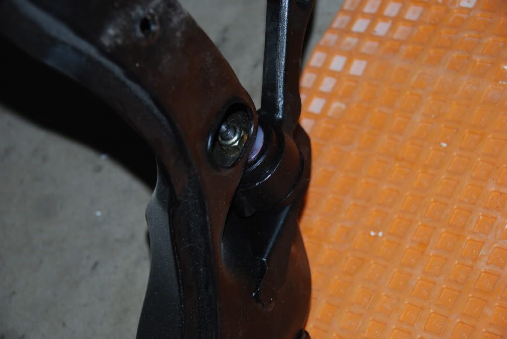
With that done, I moved to getting the updated forged control arms cleaned up and painted. This allowed me to get the poly control arm bushings lubed up and pressed in place.
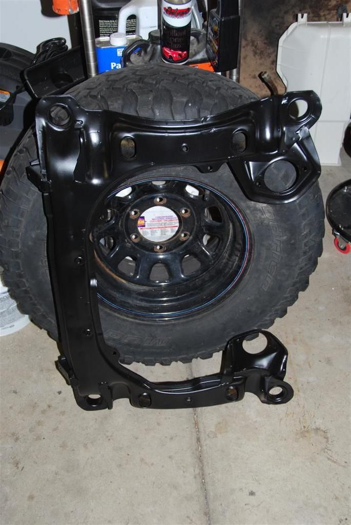
Then I assembled the subframe and got it all ready to put back on the car.
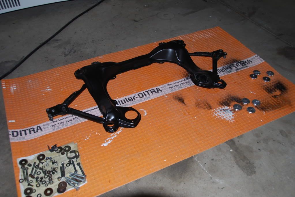
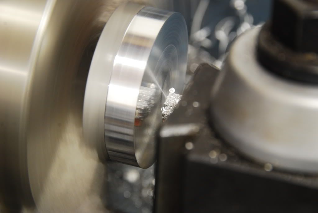
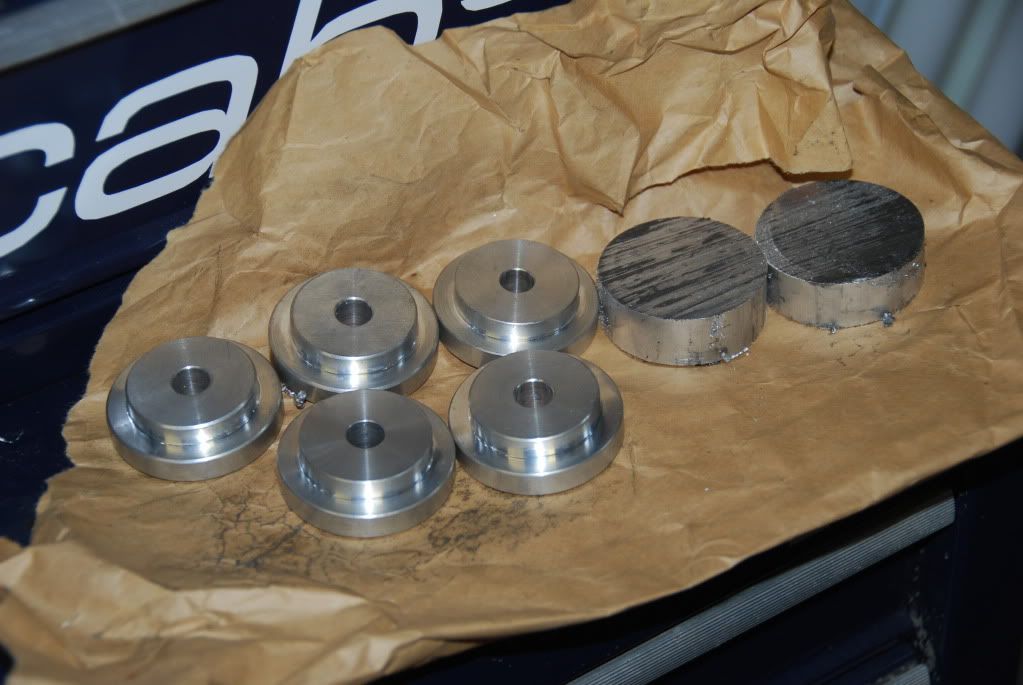
Then I made a couple sets of subframe bushings. I realize you can buy these for pretty cheap, but I can make them for pretty cheap too. I had a bunch of these made up and then I anodized them.
Facing and turning the OD on the lathe…
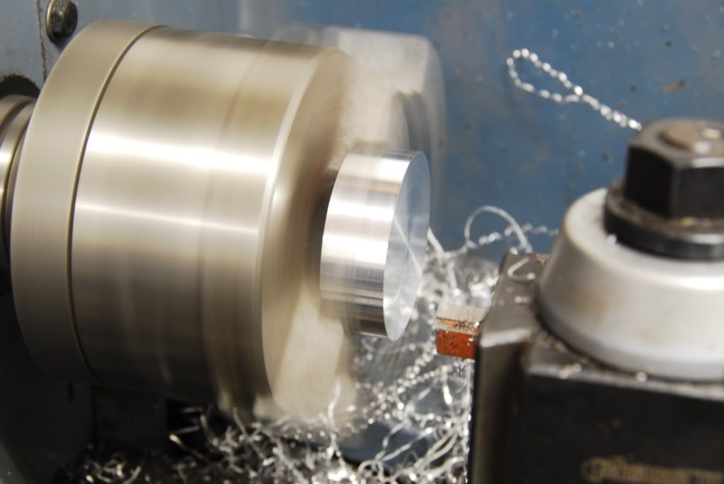
I’m by no means a machinist by trade, but I like to practice and try to get my surface finishes as smooth as possible. Not always easy with rinky dink hobby machines, but that is going to change soon.
Pretty nice to see the reflection of the tool…
Slowly turning my pile of blanks into something useful…
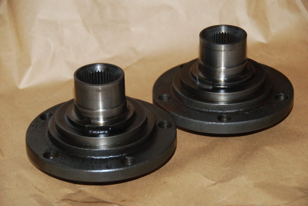
So now with the subframe mostly ready to go, it was time to turn my attention to the uprights and bearing housings. Up front, I’m using some refurbished and modified UrS hubs…
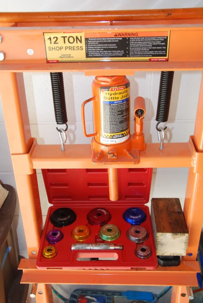
I’ve picked up a few sets of bearing housings from B320V cars with the 82mm bearing up front. I spent a couple hours pressing out the old 4 lug hubs and old bearings and was left with a pile of rusty metal…
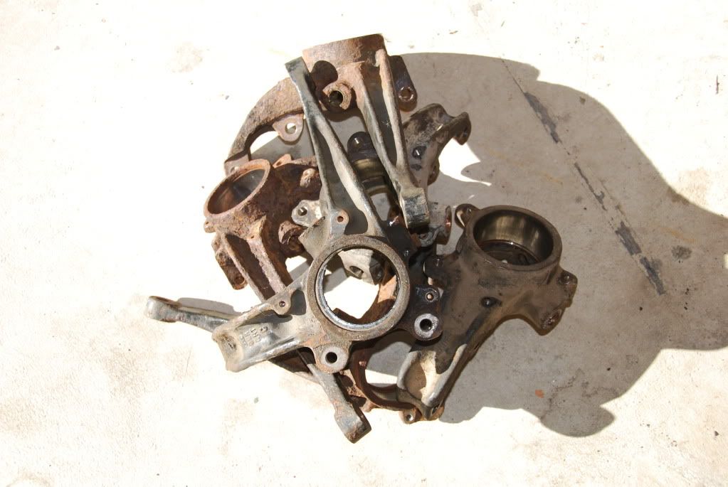
This little press and the assortment of dies makes short work of this, once you figure out how to mount the knuckles appropriately, lol
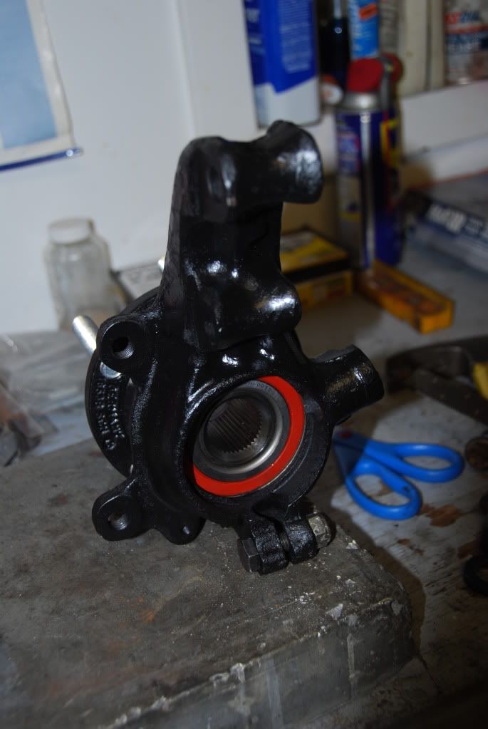
As I don’t have access to blasting equipment here, I opted to go with electrolysis rust removal on these parts by putting them in a 5gal bucket and hooking them up to my DC power supply. Add some baking soda and wait a day or two, and most of the rust flakes off. A little wire brushing and they’re ready for primer. I then painted them and pressed in some fresh bearings and clean hubs.
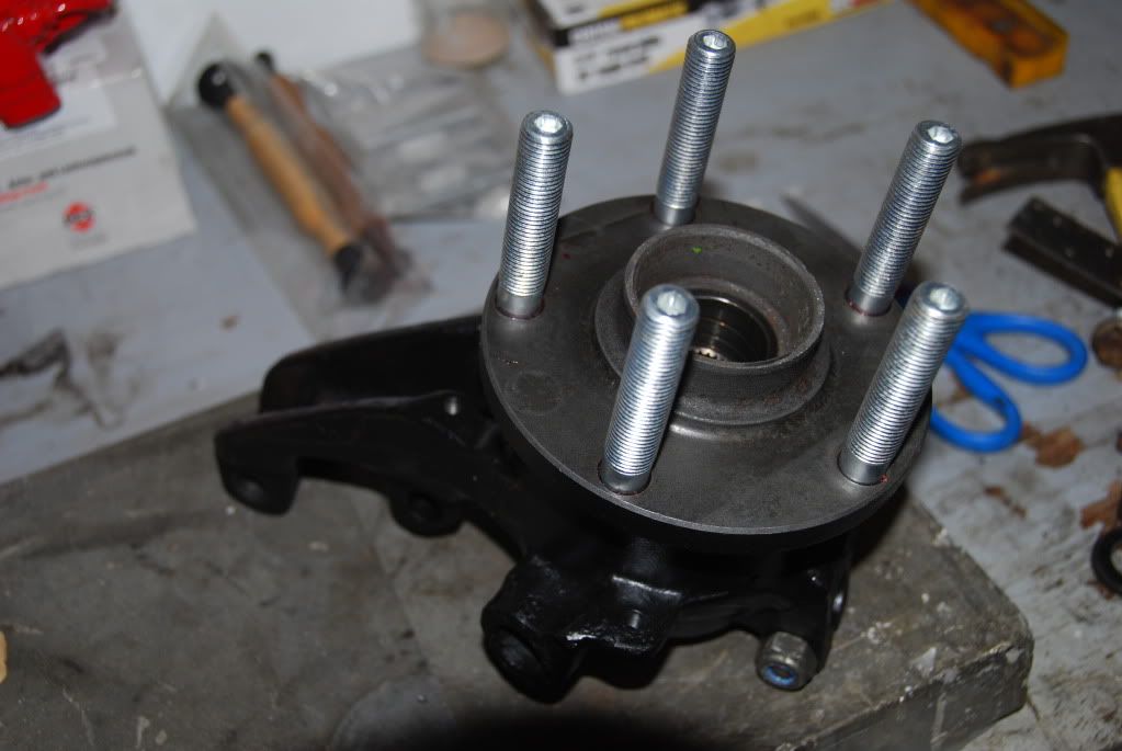
And we all hate using lug BOLTS, so I switched everything over to studs.
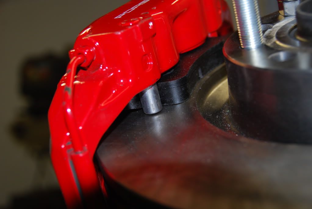
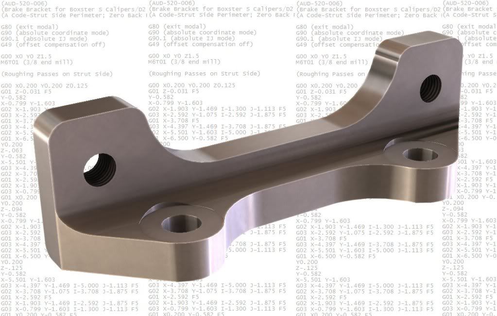
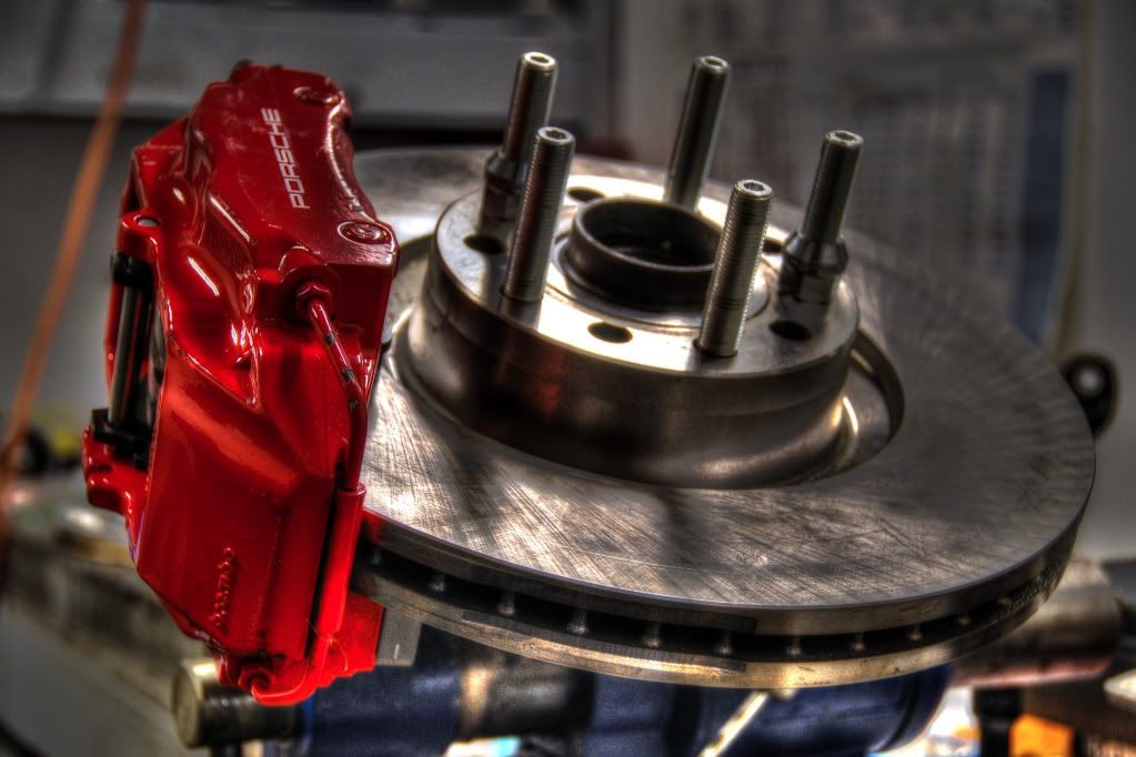
Next, I needed to figure out what to do with the front brakes. I had all of the parts, except for the caliper brackets, and figured I had better mock things up and get a solution worked out before I got too far ahead of myself. The recipe is nothing new…I’m using the B320V bearing housings, Boxster S calipers, D2A8 323X30 rotors, and UrS hubs.
This recipe requires some custom caliper brackets to work without having to add shims here and there, which I did not want to do. With this setup, the ball joint is VERY close to the inside of the rotor, but clears well enough. And I figure you can’t get any better spoke clearance than this setup.
So I mocked things up and made some measurements to get to a bracket that would put things right where I want them. I did the setup with the pins still at full length (these are typically ground down to clear the 30mm rotors as they were designed for 28mm rotors) to help center things better. I’ll likely still grind them down a bit, but they are equally clear all around…
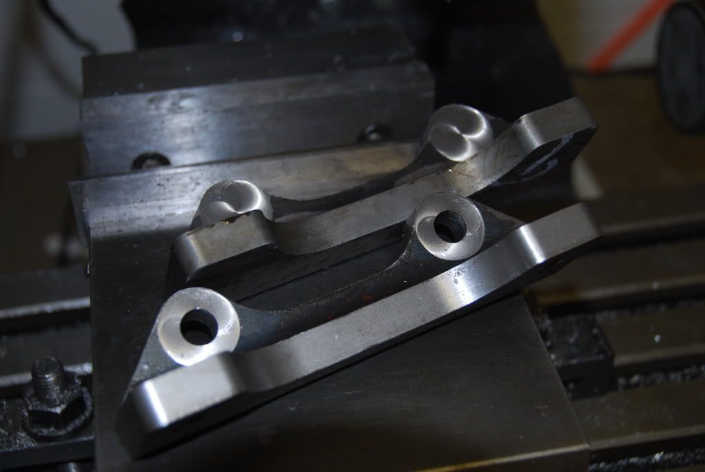
Once that was all measured and sorted out, I designed a custom bracket and generated some NC code to make the perimeter cuts…
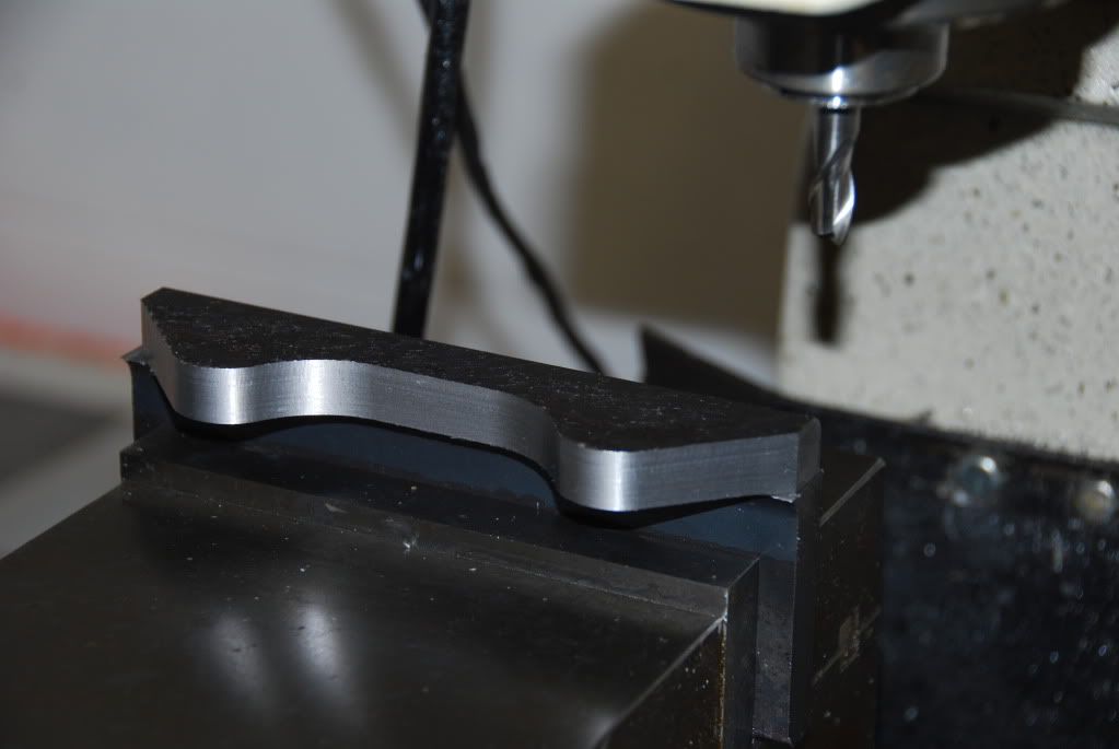
After a minor setback from a blown power supply on the motor drivers, I was able to make these cuts. I chose to do these in STEEL for several reasons and I have a nice source of material to use for them.
Just finished the finishing pass on the housing side…
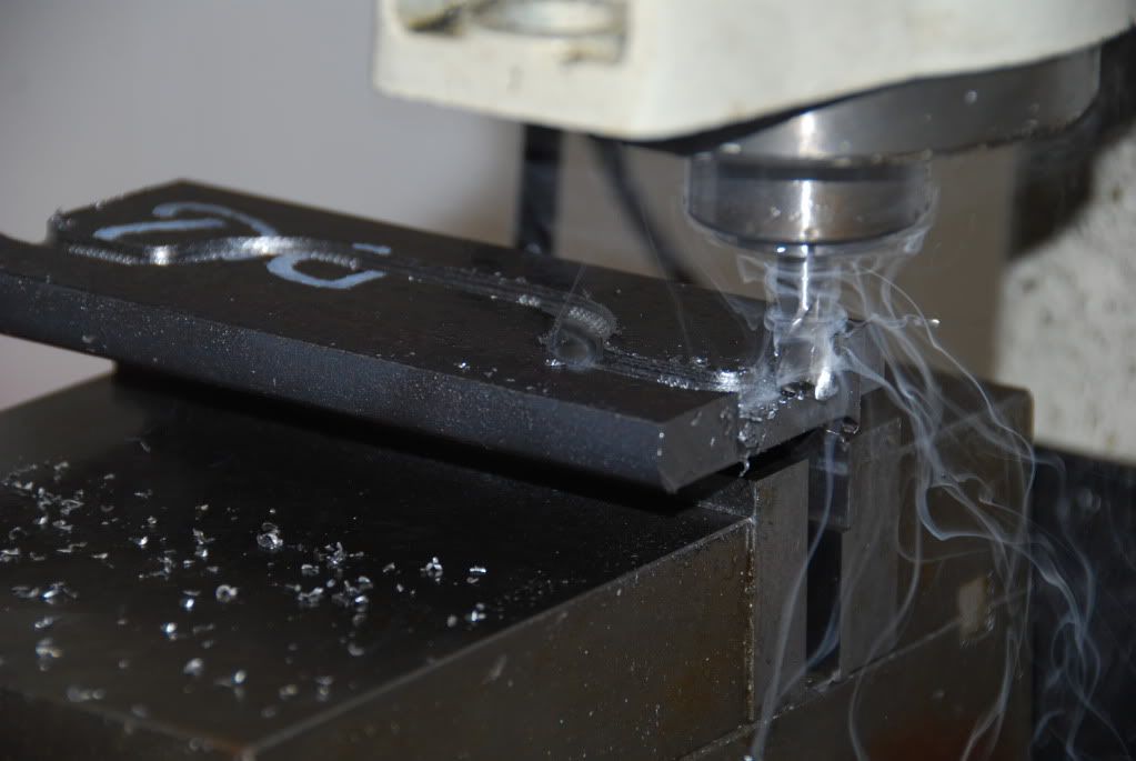
Sending some smoking chips flying while cutting the caliper side perimeter…
And after the profiling was all finished…
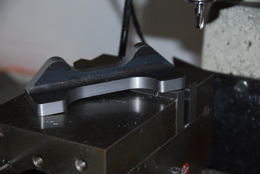
After spot facing the surface for the bracket mounting bolt, and nearly finished with the machining…
So, let’s see how they fit now…
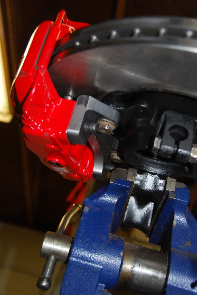
And another view…
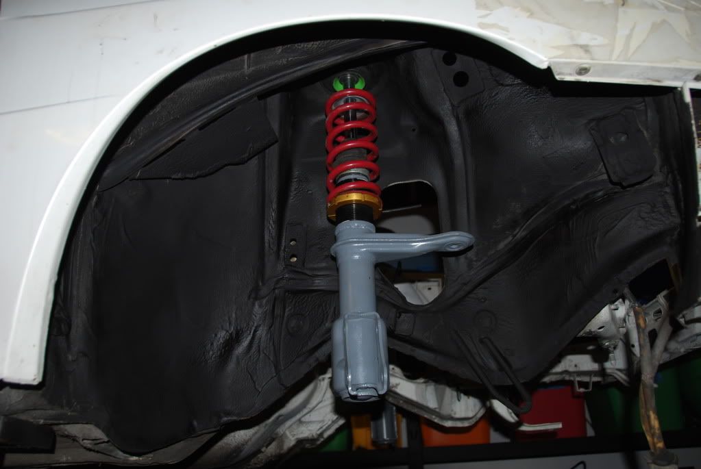
Then I got the strut upright temporarily hanging in place to make sure the color coordination was OK and nothing was clashing…
And speaking of color coordination…remember the interior of the URQ is chocolate brown, so what better choice for wheels…than flat brown…
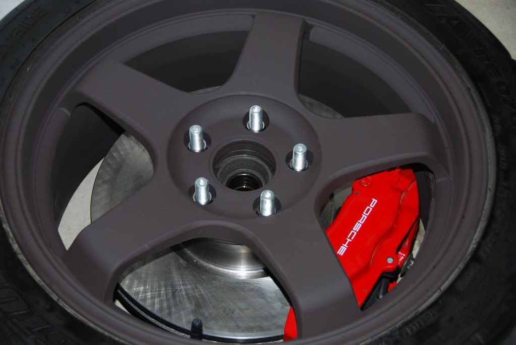
Depending on the light, the color can look a bit different…
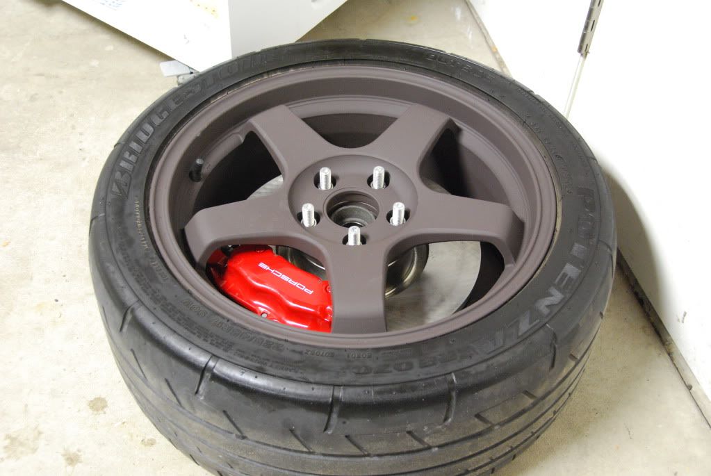
I’m guessing people will either love it or hate it…Right now, I think I love it…but we’ll see once they’re on the car.
So, I’m currently waiting on some 400 lb springs to put on the fronts and I’ll stick with the 450 lb springs in the rear. I’ve got some work to do to get the rear assemblies together, so that will be taking place over the next month or two. I also replaced my 4 player arcade cabinet with a 600 cfm flow bench and am in the process of upgrading to a larger vertical machining center (30X20X20 travels) to more easily work on larger items and not have to constantly be manually changing tools and babysitting the process to manage chip evacuation and tool temperature. I’m having to re-layout the shop to accommodate it, so that is causing a bit of a delay. I really need to expand out the back to support all of the machining and test equipment without taking away parking from the bays up front…