1983 Audi quattro-Machining the Cylinder Head
by cbrydon • August 21, 2012 • 1983 Audi ur quattro 20VT
I decided to do a test run on a damaged head to keep from damaging/destroying any of my good 20V heads.
I’ve scratched my head a few times trying to hypothesize the particular failure with this one. This is the head that came on the urs6 parts car that I picked up a few months back for a song. The story that I was told was that it recently had a head job, and then proceeded to crunch an intake valve on cylinder 1 within a few thousand miles. I would assume that the timing belt jumped or something, because it doesn’t really make sense to just drop an intake valve…at least not like a sodium exhaust valve can.
When I pulled it apart and pulled the valves, I noticed something that I couldn’t believe. This freakin’ head had been skimmed (it was definitely freshly decked, as I could see fresh tool lines) with the intake valves IN THE HEAD! If you’ve looked at many 20V heads, the intake valves are .030″ proud or so when seated. I can’t say where they sit on a new, unskimmed head as I’m not sure I’ve ever seen one, but all of the heads I’ve come across have been this way. I am in the process of trying to uncover the factory specs/dimensions on these heads so I can tell how much some of them have been skimmed, and be able to work with them a bit better.
So here are the intake valves that I pulled, minus a broken one and a bent one from Cyl.1…
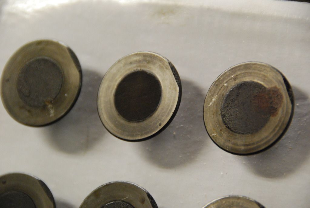
What kind of machine shop does crap like this? I’m pretty sure I know the repair shop that handled the repair, but they likely outsourced the head work to another shop. Unbelievable.
But, on with the task at hand. After measuring the critical dimensions on the MLS gasket, the block, and the head and also looking at what some of the other guys that have done this had done, I came to the dimensions that I wanted. I got the code set up and did a test run on an old 2X6. Everything looked good, so I figured I was ready to fling some chips.
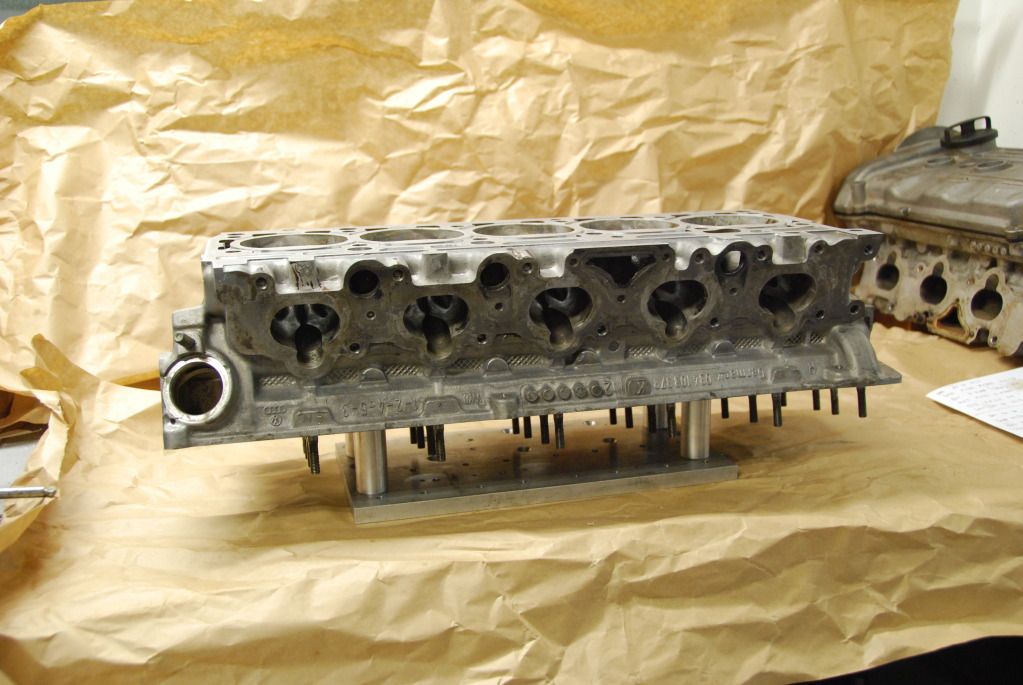
But, of course, the head doesn’t want to sit in the proper orientation and stay put by itself, so I spent a silly amount of time figuring out the setup and making a fixture. It seemed the best way was to try and rest it on the head bolt ledges, as they should be parallel to the lower deck.
So I made some little pillars to rest it on…
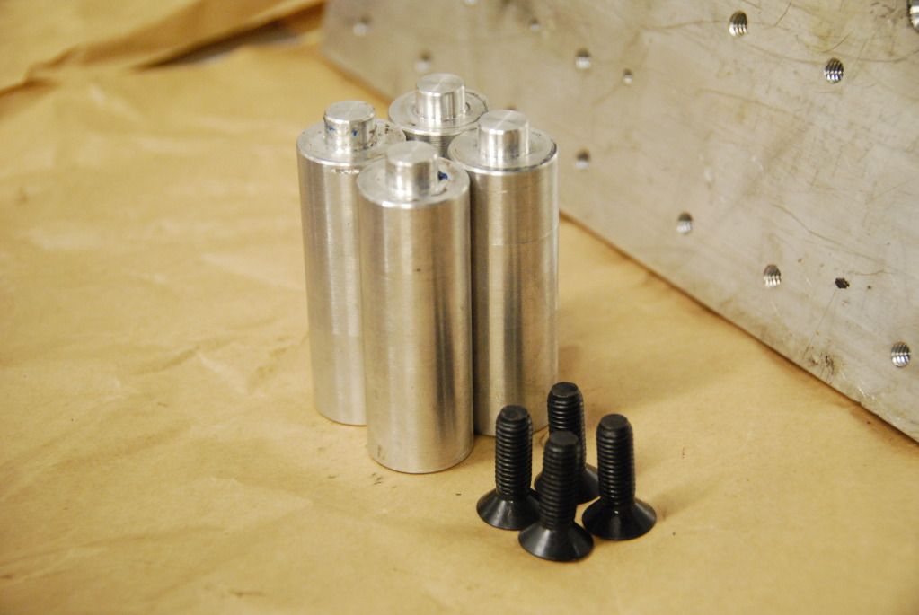
The ‘nipples’ are sized for a snug fit into the head bolt bores and the outer diameter was maximized to take advantage of as much seating area as possible. The can be mounted on a plate and moved around to work with the most appropriate location for the particular task at hand.
The fixture plate that I had around was pretty short, so it started with the locations shown here…
As configured, it is still a pain because I have to clamp the head down the the table, but it works for now. I’ll fix it when I get around to doing it for real next time. So with the head mounted to the table, I could go to town. And I quickly remembered how much fun it is to machine sticky cast aluminum. Constant air pressure and a lubed brush kept the end mill from loading up too bad, but still was a challenge. I’ve found that uncoated, high speed steel tooling works best (for my mill–no flood coolant, a bit flexy) in the aluminum as it is highly polished and very smooth, unlike many of the tool coatings available.
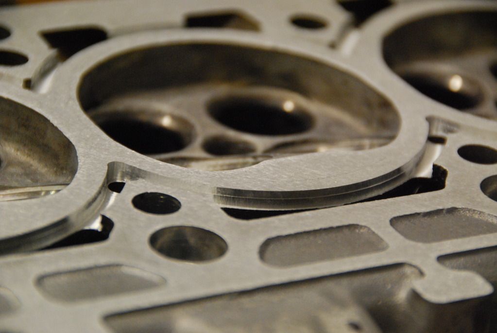
There are a few things that I will need to modify with the program, but for the most part came out as designed…
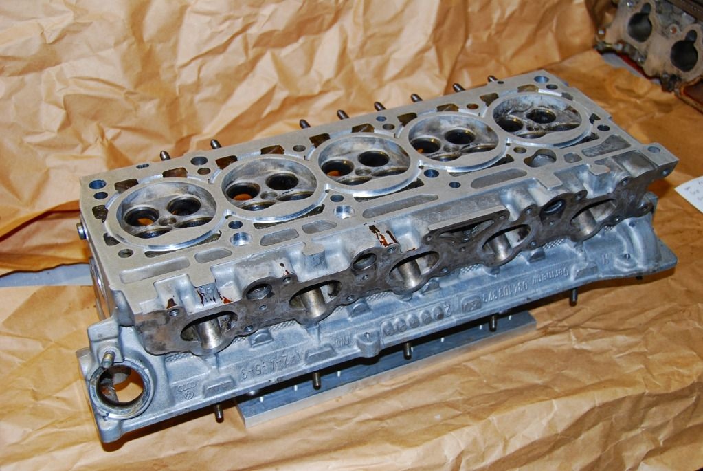
The tool loading was also causing my machine to flex a bit, as you can see with the stepover, but I don’t think the coolant will mind…
Machining the block should be much better. The cast iron machines like butter, even on my little mill.
I probably won’t get back to this for a few weeks, as I’ve now got the remaining parts to put the eS2 back together.