Audi S2 Coupe Project-More Wiring and…Running!
by cbrydon • July 31, 2010 • 1991 Audi CQ S2 Conversion
So with the main components to get the engine running in place, it was time to really get into the wiring. Here is the ‘interior’ portion of the 3B harness prior to cutting and splicing.

Splicing the 3B harness in to replace the 7A engine harness was pretty straightforward, but did require quite a few hours of studying and planning with the wiring diagrams. I have Bentley for both cars, so after a lot of page flipping and note taking, I was left with this…

Still a lot of pages, but easier to digest and work with. So then it was basically time to pull the 7A main engine harness out of the car because there was no way I was trying to just tap into things in the ‘under-the-fusebox -wiring-hell-pit.’ There are a few non-engine related things in the 7A harness that I still wanted to use (hydraulic pressure switch, hydraulic fluid reservoir level, brake reservoir level), so those pieces were pulled aside for later use.
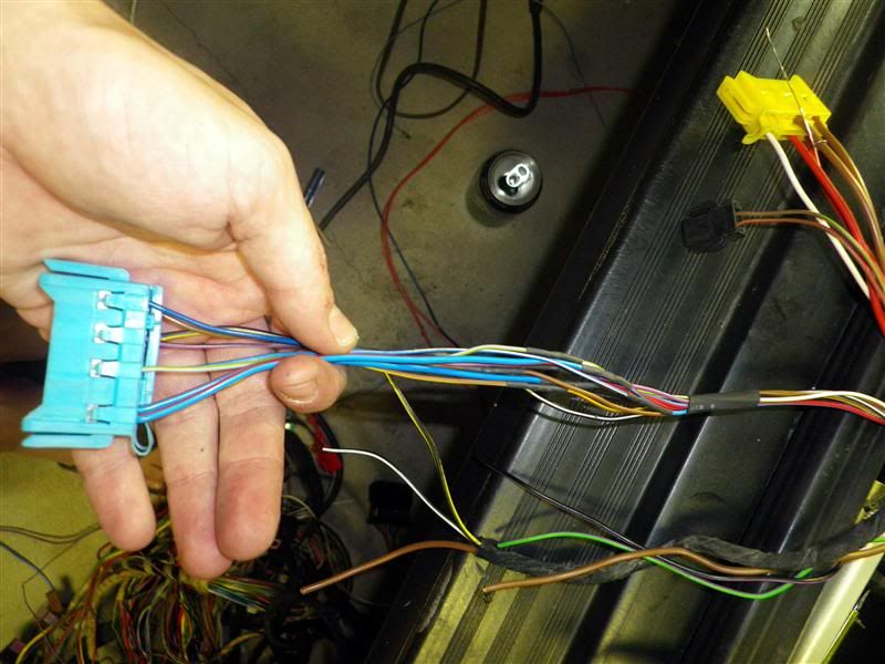
Most of the stuff interfacing the fuse box connectors (B, L, etc.) only needed some minor tweaking. I used all of the stuff from the 3B harness there. The image below shows what I salvaged for the original 7A engine harness to splice into the 3B harness. It is primarily those 4 connectors that are in the driver’s side footwell area, the t5/t10 connector that goes into the auxiliary panel and the t9 (not used). It was then just studying wiring diagrams and splicing things together. I spent A LOT of time with the diagrams as there are other things that needed to be worked on…

The car had all of the seat wiring connectors cut off when I got it, so I figured now was the time to fix that. I used some spare connectors from all of the spare wiring to plug directly into the seat bases. After some soldering and shrink tubing (staggered joints are good as shrink tubing is not as substantial as standard wire insulation and may lend to short-circuiting).
I used some gaffers tape that I had around to wrap up all of the harnesses. The ECU connector tail is shown below…

I haven’t quite decided where I’m mounting the ECU yet. Either stock (behind climate box), under, or front panel; the excess tail may dictate location for cleanliness.
So with most of the wiring complete, I figured it was time to get things a try. I still had some very old gas in the tank that needed to be pumped out. I jumpered the fuel pump relay and pumped all of the old fuel out just before the fuel filter. New gas in and a once over in the bay to make sure the necessities were there and………it starts! No cooling yet, so just idled for a bit and made sure everything was working electrically. Gauges seem to be good. Time to start really putting things back together.
I was really excited to get the interior looking presentable again. It was a long couple of years since it was in the car. So I got the new to me manual climate box in (re-foamed flaps, removed AC evap, block-off AC line outlet). Once in, I realized I didn’t hook the Bowden cables up (nor did I examine how they needed to be connected). So I struggled with hooking them up and then broke one of the clips. I remembered seeing a manual climate box at the junkyard, so I ran down and pulled that out real quick. In and working now. It then plugs directly into the existing wiring.
These are the kind of little frustrations that sometimes drive me just about crazy. Something that seems so simple can be such a PITA! There is another factor at play though. Here in SLC, it has been right around 97-100 for the last couple weeks and my car bays don’t have AC or insulation. So when it is 100 out and the sun is hitting the shingles, they get a little warm and radiate like a mofo. So surface temperatures on things inside my garage are about 115. Not really pleasant, but after about two days of cooking my head, I settled in on a saturated turbin that works awesome and looks equally retarded. Oh well, no one but me watching. Here is a pic from one of the ‘cooler’ days-mid nineties outside.

Then I put all of the other stuff back in. Overall, didn’t go too badly. The dash was a little stubborn to get into place while making sure the ducting was all engaged. So here are a couple shots with it put mostly together. I went with S2 steering wheel, S2 gauge cluster (still need to get the digital temperature display wired and functional as I lost outside temp with the removal of the GM vacubox), S2 aux gauges, VDO boost gauge in center vent (doesn’t match the backlighting of other gauges), manual climate controls, and carbon interior trim (not yet installed on door panels)


Now with most of the interior together (I still left a service loop in the harness to make any necessary changes or additions), it was time to get the ancillaries all hooked up. First, I wanted to get the cooling lines all installed. I have the silicone kit from 034 and everything fits pretty well. I needed to make a couple tweaks due to the afterun pump and the modified coolant pipe exit. I used a 90 fitting and some hose to run from the coolant pipe to the pump. This locates it roughly in the S2 stock location. It is ziptied in place for now.

Here are some engine bay shots as it stands currently. Still some cleaning up to do, but I’m not going to get ahead of myself.


Somewhere during this period, I was cleaning up the garage a bit and couldn’t just clean up around this thing again. It was basically an empty cabinet that I inherited from a friend a couple years ago. I had planned to throw a PC and MAME in there from the beginning, but it was just one of those constantly bumped projects. I also had this old 27” CRT TV laying beside it that was supposed to go into it. Well, I just couldn’t clean around it anymore and I had most of the pieces to do it, so…a couple days later and I’ve got some 4 player action…Gauntlet anyone? Good for a break now and then.

Yesterday I dove into the radiator cooling fan control and what needed to be done there. I have the 500W fan and ABY shroud so I need to modify things a bit to work right. I didn’t get the resistors from the 200 donor (Doh!), so I just got another stock resistor (~ 1 ohm or so) to put into the circuit. Now the afterun circuit runs through both resistors, low speed through one resistor, and high speed through my fused relay run off of the alternator terminal. I think it should all work like that.

I had a credit at 034 so I picked this up to do the job. Not sure if I like it or not. I think only the 60A is switched.

A few years ago, I got the 3” downpipe and exhaust from 034. I finally installed it yesterday. I am a bit disappointed in fitment, as it “Will fit all 80/90/Coupe Quattro vehicles with no modifications”. There is minor interference on the front flex coupling and the transmission mount. That will require downpipe modification. From what I can tell, the STR manifold had the same positions as stock manifold. I’m not certain what they use for fixturing.

Then the length of the main section seems to be about 2-3” too short based on the CV flange clearance hump. This is also shown in the rear where the pipe is hitting the inner tie rod mount. I planned on putting in a race cat (v-banded with test-pipe option), so that should fix that problem as I can adjust overall length there. Then the v-bands seem to be warped and don’t seal, even with clamps crank uncomfortably tight. I may need to use sealing gaskets here. No biggie.


I guess I’ll finish it off with a nice battery shot. This will need to be mounted back here somewhere, but I’m not sure yet. So there is still a lot to do, but this progress is also spawning motivation, so I hope to be out driving to some capacity soon.

…And one more thing if you were able to make it all the way through this post…